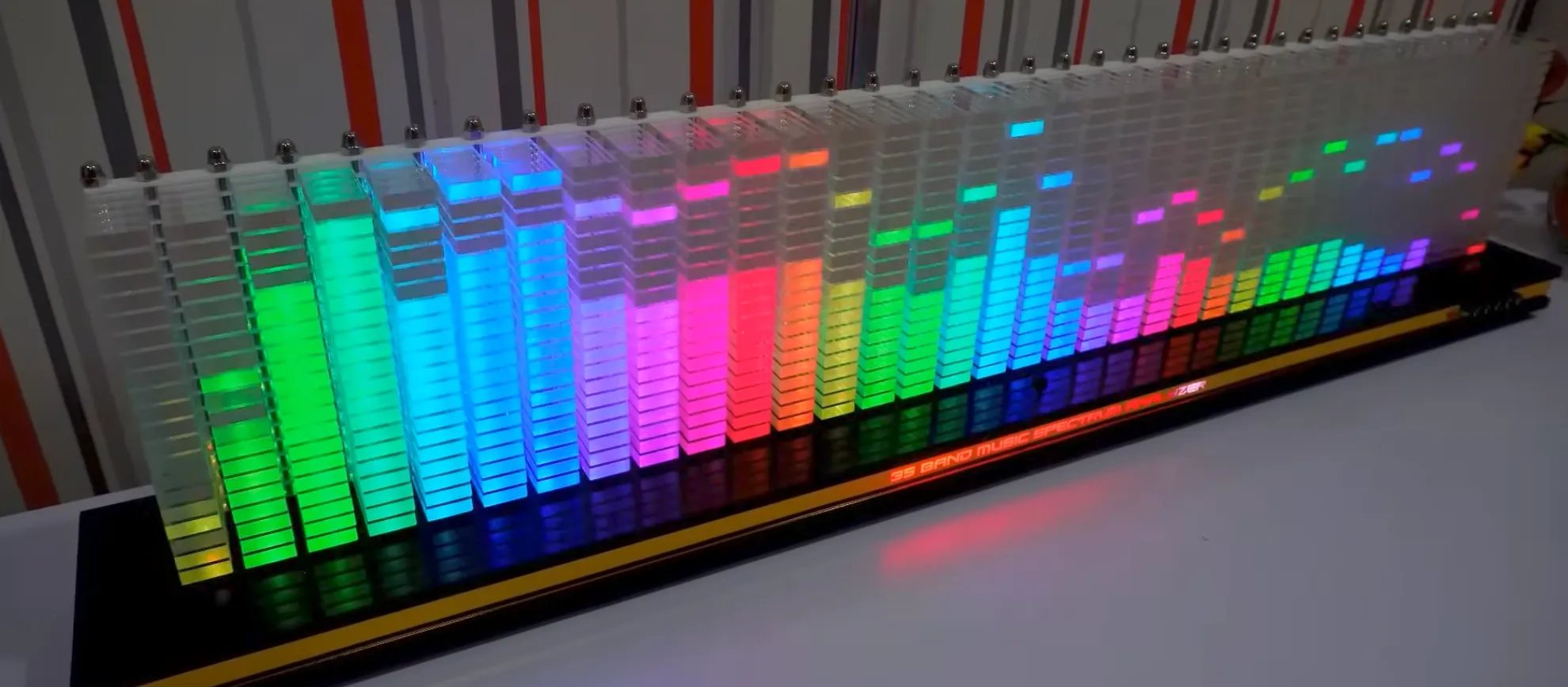
Music Spectrum Analyzer
A 32-band acrylic spectrum analyzer for a home sound system, in progress: FFT-based DSP on a Teensy 4.1 tapping S/PDIF from a PC or a Bluetooth receiver, driving 640 WS2812 LEDs over OctoWS2811.
I wanted to actually see music, physically, on the wall, so I’m building a 32-band spectrum analyzer: an acrylic panel of LED columns that turns live audio into a real-time frequency display, sitting next to my actual sound system rather than replacing it. It’s a work in progress, and it’s as much a signal-routing problem as a DSP one.
Signal path
The core is a Teensy 4.1 doing the FFT in software. I picked it over an ESP32 specifically because I ended up needing two input paths, wired S/PDIF from a PC and Bluetooth from a phone, and no single chip does both well: Bluetooth Classic (A2DP) only exists on the original ESP32-WROOM-32, while USB Audio Class only exists on the Teensy and ESP32-S2/S3. Rather than fight one chip into doing both, wired audio became the Teensy’s native job and Bluetooth got bolted on as an external receiver module instead of a second microcontroller.
The default 1024-point FFT gives 43Hz per bin at 44.1kHz, which makes the bottom few bands look mushy and correlated, so I’m running a 4096-point transform with CMSIS-DSP instead, around 10.8Hz per bin, using the Teensy 4.1’s hardware FPU. The 640 WS2812 LEDs are arranged as a 32-by-20 matrix and driven with OctoWS2811, which splits the strip across 8 parallel outputs on FlexIO and DMA so frame rate isn’t capped by pushing 640 pixels down one wire.
Getting audio in
Two sources need to reach the analyzer, my PC over USB and my phone over Bluetooth, without either one touching the actual listening path.
The PC connects over USB-C to a FiiO K11 R2R DAC I already own. Its line out feeds my Denon UDRA-M7 amp and Klipsch R-41 speakers exactly like normal, and because the K11’s coax jack outputs a live S/PDIF copy whenever it’s in USB mode, that same connector doubles as a free digital tap for the analyzer.
The phone connects over Bluetooth to a 1Mii B06HD+ receiver, which puts out optical and coax S/PDIF at the same time, the one spec worth actually confirming before buying, since most cheap receivers switch between outputs rather than running both at once. Optical goes into the K11’s optical input so Bluetooth plays over the same DAC and amp; coax goes down to the analyzer as its second candidate feed.
The Teensy only has one S/PDIF input, so a toggle switch on the front-end board picks between the two coax sources before either signal gets processed, rather than building a receiver circuit for each and muxing the clean logic afterward. On the selected line: a 75-ohm termination and a DC-blocking cap knock the ~0.5Vpp coax signal down to something usable, then a 74LVC1GU04 inverter, wired with a 100k-ohm feedback resistor so it biases into its linear region, acts as a comparator and squares that into clean 3.3V logic for the Teensy’s S/PDIF input on pin 15.
The analyzer is a tap, not a link in the chain. It never sits between a source and the speakers, so unplugging it, or it crashing, doesn’t touch playback either way. The one thing it doesn’t get for free: the tap point is upstream of both the K11’s and the Denon’s volume knobs, so bar height doesn’t track volume yet.
Power and wiring
640 WS2812s pull close to 38A at full white, though a spectrum analyzer never gets near that. I sized the supply for the worst case anyway with a Mean Well LRS-150-5 (5V, 30A), fused on the output. Power goes straight to the LED strips rather than through the Teensy, injected at both ends of each 80-LED run with a 1000uF capacitor at every injection point, since voltage sag along a run is what makes the far end drift orange. Teensy, OctoWS2811, and the power supply all share one ground point, and the Teensy’s VIN-VUSB pads get cut since it’s powered off the LED rail rather than USB, so it can’t backfeed into my PC.
CAD and mechanical design
The acrylic enclosure and mounting hardware are modeled in SolidWorks, including the individual rows that hold each LED column. I wanted to build this project for basic CAD/mech skills and to have a cool visual alongside my speakers!
Sourcing the acrylic
The panels are full 48”x96” cast acrylic sheets, big enough that picking them up meant renting a U-Haul rather than fitting them in my car. The mechanical side of this build has been slow moving: sourcing material, finishing the row drawings in SolidWorks, and getting everything cut is taking longer than the electronics.
Status
WIP. The front-end board, the S/PDIF receiver circuit and source-select toggle, is the current focus: it’s the one part of this build that isn’t just wiring known-good modules together, so I want it proven on the bench before committing to an enclosure. The LED matrix and CAD are modeled and waiting on the electronics to settle. Real photos and captures will land here as the build progresses.